Suitable installation location
Lifting systems in the floor slab can often be found in equipment rooms, bicycle storage rooms, cellars or ancillary rooms. Sometimes they are also located directly in underground car parks. In this case, it is important to ensure that the chamber cover can be driven over.
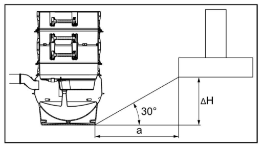
The chamber must not be installed in locations where it could influence adjacent foundations, i.e. minimum distance a = distance between the bottom edge of the chamber and bottom edge of the foundations:
a = ΔH x 1.73
Installation depth
The exact installation depth must be determined during planning. This usually results from the main drainage pipe, which is routed below the floor slab with a gradient to the lifting station. The total depth from the upper edge of the floor to the bottom of the main drainage pipe at the inlet to the lifting station must be determined. This measurement is used to determine the exact product configuration.
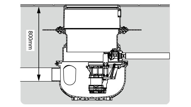
The Aqualift S Compact and Aqualift F Compact lifting stations from KESSEL, whose chamber is not accessible due to their compact size (LW 400), may not be installed deeper than 80 cm due to accessibility for maintenance purposes (measured from the upper edge of the floor to the bottom of the main drainage pipe at the inlet).
Groundwater
With pumping stations in the floor slab, the immersion depth of the chamber in the groundwater must be taken into account and tested with the selected product. Most KESSEL pumping stations and lifting stations may be immersed up to 3 metres into groundwater without any additional measures to prevent buoyancy.
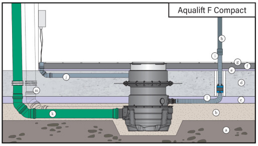
1. Inlet pipe (main drainage pipe)
The inlet pipe to the lifting station must be designed in accordance with the applicable standards and installed accordingly. All pipes must be routed so that they can run empty automatically. The pipes must not be narrowed in the direction of flow. Changes in the direction of main drainage or collecting pipes may only be carried out with bends ≤ 45°. Transitions to larger nominal widths must be made with transition fittings or other suitable connections (e.g. transition gaskets). Eccentric transition fittings should be installed at the same level in collecting connection pipes. To make inspections easier, installations in main drainage pipes must be flush with the bottom.

The pressure pipe connection is made of PE DN 80 (OD = 90 mm). KESSEL recommends the connection of standard
PE-HD electro-welded sockets.

Alternatively, the pressure pipe can also be connected using standard clamp connectors (see KESSEL accessory art. no. 28090/28091/28092).
2. Pressure pipe
The pressure pipe for lifting stations in the floor slab must be routed from the lifting station to the nearest reference point in the room. This is usually done under the floor slab up to the next wall. At this point, the pressure pipe is routed through the floor slab. In the case of a waterproof floor slab, the duct through the floor slab must be sealed. This can be achieved using a lining pipe with a sealing insert or a puddle flange. Pressure pipes beneath the floor slab are exposed to the ground and must be suitable for this. Pressure pipes made of PE-HD or PVC are used here. The KESSEL pressure pipe set ( accessories) can be used for smaller pressure pipe dimensions (up to DN40/OD50). KESSEL recommends connecting a standard HD-PE pipe for larger pressure pipe dimensions (from DN40/OD50).
3. Ventilation pipe
- The ventilation pipe is connected directly to the tank in lifting stations in the floor slab. Direct connections or scored areas are provided for this purpose depending on the type of system.
- The ventilation pipe must be routed from the lifting station to the nearest reference point in the room. This is usually done under the floor slab up to the next wall. At this point, the ventilation pipe is routed through the floor slab.
- In the case of a waterproof floor slab, the duct through the floor slab must be sealed. This can be achieved using a lining pipe with a sealing insert or a puddle flange.
- Ventilation pipes beneath the floor slab are exposed to the ground and must be suitable for this. A standard KG or KG2000 pipe is therefore used here. The smallest available size is DN 100. This allows the DN 100 ventilation pipe to be routed beneath the floor slab. Later, inside the building, the ventilation pipe can also be routed further with a HT pipe (or similar) in at least DN 70.
4. Cable duct
- The cable duct is connected directly to the tank for lifting stations in the floor slab. Direct connections or scored areas are provided for this purpose depending on the type of system.
- It must be routed with a slight gradient (we recommend 1-2%) to the lifting station so that any condensation can drain away and the cables do not lie in water permanently.
- In the case of a waterproof floor slab, the duct through the floor slab must be sealed. This can be achieved using a lining pipe with a sealing insert or a puddle flange.
- Cable ducts beneath the floor slab are exposed to the ground and must be suitable for this. A standard KG or KG2000 pipe is therefore used here. The smallest available size is DN 100. This allows the DN 100 cable duct to be routed beneath the floor slab.